Contact us for quotation
Let's have a chat

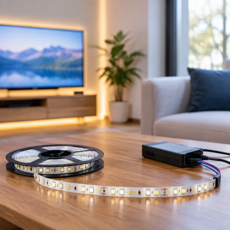
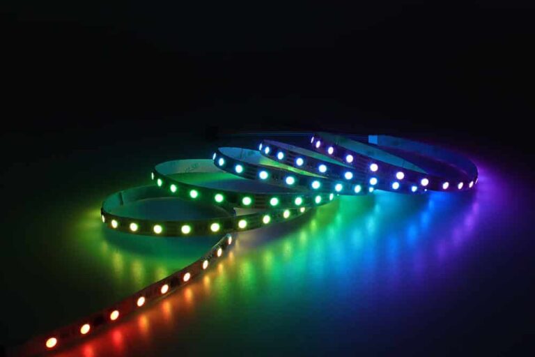
Voltage drop occurs when electrical potential decreases as direct current (DC) travels along the conductive traces of a flexible printed circuit board (PCB) or connecting wires. In low-voltage DC LED installations, internal electrical resistance naturally opposes current flow, leading to a progressive loss of voltage between the power source and the far end of the run.
Accounting for these mechanical and electrical factors is the essential first phase of an accurate LED strip voltage drop calculation, ensuring every layout delivers stable, balanced power throughout the circuit.
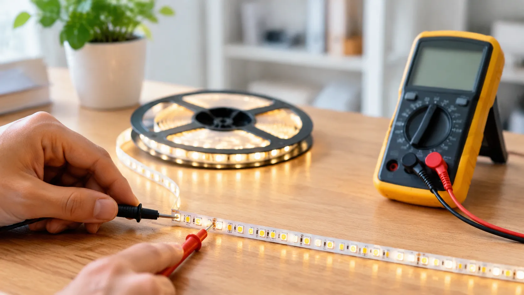
To master your LED strip voltage drop calculation, you only need basic physics: Ohm’s Law. Voltage drop is simply the electrical potential lost as current travels through the conductive traces of the strip or lead wires.
The baseline formula is straightforward:
Voltage Drop (V) = Current (I) × Resistance (R)
Here is how we break down the calculation into actionable steps for any low-voltage installation:
First, determine the total current running through your circuit. Divide the total wattage of your LED tape by its operating voltage:
Resistance depends on the length of the run, the copper thickness (such as 2oz or 3oz PCB), and the gauge of your extension wiring. For standard copper conductors, total resistance is calculated as:
Multiply your total current by the calculated resistance:
Subtract the dropped voltage from your power supply’s starting voltage to find the final delivery voltage at the tail end:
| Starting Voltage | Acceptable Drop (3%–5%) | Minimum Tail Voltage |
|---|---|---|
| 12V DC | 0.36V – 0.60V | 11.40V |
| 24V DC | 0.72V – 1.20V | 22.80V |
| 48V DC | 1.44V – 2.40V | 45.60V |
If your calculated loss exceeds 5%, the LEDs at the end of the run will visibly dim and run warmer near the feed point. For larger architectural layouts, consult our guide on understanding LED strip voltage drop or review proper lead planning when connecting an LED strip to a power supply to ensure balanced voltage throughout the line.
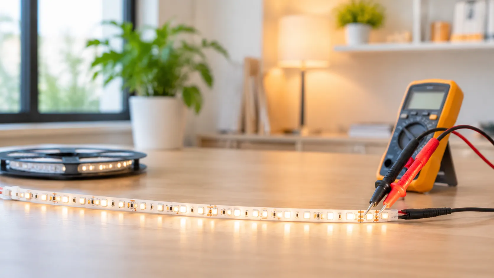
When an LED installation suffers from uncalculated voltage loss, the results show up immediately in both visual quality and hardware durability. Neglecting an accurate LED strip voltage drop calculation does not just cause a slightly dimmer room; it systematically degrades your lighting setup from both ends.
The most obvious symptom is uneven light distribution across the run. Because voltage decreases as distance increases along the copper trace, the LEDs farthest from the power supply receive significantly less power than the first few diodes.
Voltage drop affects diode chemistry unevenly. Different color diodes and phosphor blends require specific forward voltages to produce accurate hues.
Voltage drop forces an uneven electrical load across the circuit board:
Once your LED strip voltage drop calculation shows a loss greater than 3% to 5%, you need to adjust your circuit layout before finalizing the installation. We use five reliable methods across commercial and residential projects to maintain full brightness and color consistency from the first diode to the last.
Connecting power leads to both ends of an LED strip cuts the path length of the electrical current in half. This closed-loop configuration balances the load across the entire run:
Daisy-chaining multiple strips end-to-end forces all current through tiny PCB copper traces, generating heat and heavy loss. Running a secondary main bus wire parallel to your run lets you tap fresh power directly into the circuit at set intervals. To preserve the long-term reliability and benefits of LED tape strip installations, inject power every 5 meters for 12V tapes and every 10 meters for 24V tapes.
Operating at 24V or 48V instead of 12V is the simplest way to reduce loss at the planning stage.
Long lead wires between the power supply and the strip often cause noticeable drops before the current even reaches the first LED.
Instead of connecting strips together in a single continuous series, split long layouts into parallel branches powered from a central location.
| Wiring Method | Max Recommended Run (12V) | Max Recommended Run (24V) | Voltage Drop Risk |
|---|---|---|---|
| Single-End Series Feed | Up to 5 meters | Up to 10 meters | High |
| Dual-End Feed (Both Ends) | Up to 10 meters | Up to 15 meters | Moderate |
| Parallel Central Split | 5 meters per branch | 10 meters per branch | Low |
| Continuous Bus Injection | Unlimited (sized to wire) | Unlimited (sized to wire) | Extremely Low |
When I plan extended runs for commercial or residential architectural layouts, continuous power injection often becomes messy, labor-intensive, and visually distracting. Even after you dial in an exact LED strip voltage drop calculation, running parallel wires every 5 to 10 meters adds substantial material and labor costs. Constant current (CC) LED strips solve this problem right at the circuit board level.
Standard constant voltage (CV) strips rely solely on basic resistors. As DC voltage drops down the copper traces, the current flow to each diode declines, leaving the far end dull and discolored.
Constant current strips integrate tiny onboard integrated circuits (ICs) along the tape:
| Feature | Standard Constant Voltage (CV) | Constant Current (CC) Integrated Strips |
|---|---|---|
| Max Single-End Run | Typically 5m (12V) or 10m (24V) | 10m to 20m+ (depending on model) |
| Tolerance to Voltage Drop | Low (direct dimming as voltage falls) | High (uniform output despite line drop) |
| Wiring Complexity | High (demands regular power injection) | Low (single-end or simple dual-end feed) |
| Installation Labor | Higher labor and extra conduit work | Quick, clean, streamlined deployment |
Relying on low-grade tape with insufficient copper weight is one of the classic mistakes installers face; learning how to steer clear of common traps in the purchase of led strips ensures you specify the right trace thickness and drive architecture from day one.
If your installation requires long, seamless architectural lines without the clutter of repeated junction boxes and messy return lines, switching to constant current tape eliminates the headache of line loss entirely.