The increasing popularity of LEDs has led to the widespread adoption of PWM dimming. With it, you can precisely control LED brightness, extending functionality and achieving energy savings.
However, you might have heard of it, but how exactly does it work, and why is it so effective? In this guide, I will break down how it controls LED brightness, why it’s preferred over other methods, and more. Let’s get started–
Table of contents
Hide
Brief Overview Of The Development Of LED Technology
LEDs or Light Emitting Diodes come with high brightness solutions that surpass traditional incandescent and fluorescent lighting. Basically, they have better efficiency and longevity than other lighting.
Besides, the development of semiconductor materials and improvements in LED manufacturing have led to LEDs that can create a wide range of colors and brightness levels. This has changed the way we use lighting in different places. One of the most significant breakthroughs in LED technology has been the development of dimming capabilities. Unlike conventional light sources that dim by reducing voltage, LEDs require more sophisticated control to achieve smooth and flicker-free dimming. This led to PWM dimming, which allows precise control over LED brightness while maintaining energy efficiency and color accuracy.
What Is PWM (Pulse Width Modulation)?
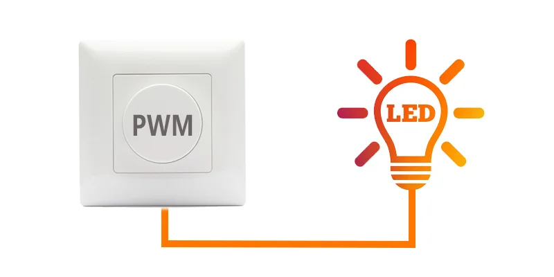
PWM, or LED Pulse Width Modulation, is widely used to control the power supplied to electrical devices, mainly LEDs. By rapidly turning the power on and off, PWM controls the perceived brightness of the LED without affecting its efficiency or color. This technology has become a go-to solution for LED dimming due to its precision, efficiency, and ability to maintain consistent light quality.
Basic Concept Of PWM
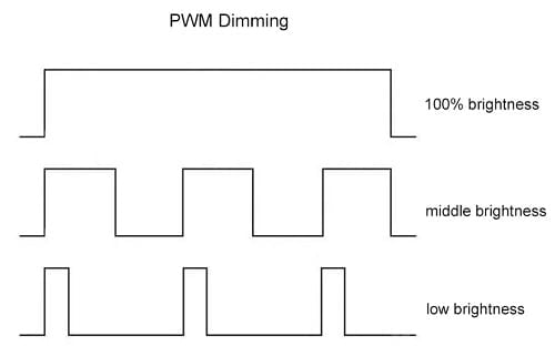
Basically, PWM involves creating a signal that oscillates between “on” and “off” states in a consistent cycle. The critical factor in PWM is the duty cycle, which represents the percentage of time the signal is “on” within each cycle.
For example, if a PWM signal has a duty cycle of 50%, the LED is on for half of the time and off for the other half in each cycle. By adjusting the duty cycle, you can control how much power is delivered to the LED, influencing its brightness.
The beauty of PWM lies in its simplicity. By keeping the frequency of the on-off cycles high enough (usually above 100 Hz), the human eye perceives a smooth, continuous light rather than a flicker. This allows for extremely precise dimming, with the brightness level controlled by altering the ratio of “on” time to “off” time within each pulse.
Working Principle: How Brightness Is Adjusted By Changing Pulse Width?
The term “pulse width modulation” refers to adjusting the width, or duration, of the “on” pulses. By changing the pulse width, you can control the LED’s brightness.
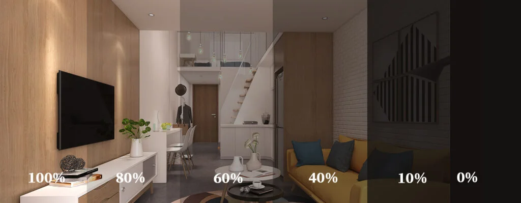
Higher Duty Cycle (Longer “On” Time): When the duty cycle is increased, the LED stays on for a longer period during each cycle. For example, a 90% duty cycle means the LED is on for 90% of the time and off for just 10%, producing almost full brightness.
Lower Duty Cycle (Shorter “On” Time): Conversely, reducing the duty cycle shortens the time the LED is on, resulting in a dimmer light. For instance, a 10% duty cycle means the LED is on for only 10% of the time and off for 90%, resulting in much dimmer light.
Comparison Of PWM With Other Dimming Methods
To understand why PWM is so effective for LED control, it helps to compare it to other standard dimming techniques. One notable method is linear dimming, also known as analog dimming.
- Linear Dimming (Analog Dimming): Linear dimming directly reduces the current supplied to the LED to lower its brightness. As the current is reduced, the LED emits less light, resulting in dimming. While this may seem like a straightforward approach, it comes with several drawbacks:
- Inconsistent Color Temperature: One major disadvantage of analog dimming is that the color temperature of the LED can shift as the current changes. LEDs tend to produce warmer tones when dimmed via linear dimming. This can be undesirable in settings that require consistent lighting.
- Lower Efficiency and Heat Generation: As the current is reduced, the LED’s efficiency can drop, and more heat may be generated. This can potentially decrease the lifespan of the LED and increase the risk of damage.
- Limited Dimming Range: Analog dimming can also have a limited dimming range and may not smoothly achieve deficient light levels.
Why Is PWM Dimming Preferred For LEDs?
Due to its precision, efficiency, and consistent color and brightness, PWM dimming has become the preferred method for controlling LEDs. It allows for smooth, flicker-free dimming and is compatible with various control systems. This includes digital and smart home technologies. This makes it versatile enough for any environment, from residential to commercial to industrial settings.
The proper dimming can significantly enhance your LED lighting system, comfort, and energy savings. With PWM dimming, you gain complete control over brightness levels. Also, this ensures your lighting can adapt seamlessly to different needs and environments.
Advantages Of PWM Dimming
There are several advantages to PWM dimming. For instance–
1. Energy Efficiency
The primary benefit of PWM dimming is its high energy efficiency. Unlike linear dimming, which lowers the current supplied to an LED and can lead to wasted energy, PWM modulates the duty cycle to control brightness. This method ensures that the LED is either fully on or entirely off during each cycle, allowing for efficient energy usage.
By reducing the “on” Tim” o” the LED w” the” ut a “te” in the current, PWM achieves significant energy savings. For example, when the duty cycle is set to 50%, the LED consumes only half the power it would at full brightness.
As a result, even at lower brightness levels, PWM dimming maintains high efficiency. And it allows for reduced energy consumption and lower electricity costs over time. This efficiency is crucial in commercial settings. Hence, you can use them where lighting is often used for extended periods, and in smart home systems seeking to minimize their carbon footprint.
2. Heat Management

Heat management is critical for LED performance, as excessive heat can lead to reduced light output, color shifting, and shorter fixture lifespans. Traditional dimming methods, whether analog or resistor-based, can generate significant heat due to their control of current flow. This heat buildup can damage LED components and lower overall efficiency.
However, PWM dimming dramatically improves heat management. PWM minimizes the heat generated during operation by quickly switching the LED on and off instead of continuously reducing current. Since the LED is fully on when active, it operates within its optimal temperature range. The short off-cycles allow the LED to dissipate heat more effectively, maintaining a stable operating temperature.
The result is reduced thermal stress on the LED and its components, ensuring stable performance over time. For environments where lighting needs to be on for extended periods, such as warehouses or outdoor spaces, PWMs improve both performance and longevity.
3. Extended Lifespan Of Lighting Fixtures
The way LEDs are dimmed has a direct impact on their lifespan. LEDs are renowned for their long operational life, often lasting tens of thousands of hours when properly maintained. However, the wrong dimming technique can reduce this lifespan by causing excess heat, current surges, or unstable operation.
PWM dimming extends the lifespan of LED fixtures by ensuring optimal performance under various lighting conditions. Because PWM dimming maintains a constant current to the LED and only adjusts the duty cycle. It prevents the wear and tear associated with fluctuating or reduced currents in analog dimming. The rapid on-off cycling reduces the average power load on the LED.
Moreover, as mentioned earlier, the improved heat management from PWM dimming further contributes to an extended lifespan. By preventing overheating and reducing the risk of thermal degradation. With PWM dimming, LEDs can consistently achieve their maximum rated lifespan.
4. Better Color Fidelity
Color fidelity refers to an LED’s ability to maintain a temperature across varying brightness levels. And the main issues with analog or linear dimming are that as the current decreases, the LEDs’ temperatures shift. As a result, you will get a warmer or less accurate hue at lower brightness.
This color shift can be undesirable in settings where consistent lighting quality is crucial, such as retail displays, photography studios, and medical facilities. However, PWM dimming excels in maintaining consistent color fidelity across the entire dimming range. Because PWM controls brightness by altering the duty cycle rather than changing the current. The LED always operates at its optimal current when it is “on.” The “s e” ensures the” the” li” ht “output retains its intended color temperature, regardless of the brightness level. The result is consistent color quality, whether the LED is at full brightness or dimmed to a lower level.
For applications where color accuracy and light quality are paramount. For instance, in restaurants, high-end retail stores, art galleries, and film production, PWM dimming is an invaluable solution. This ensures that LED lighting provides a uniform and pleasant color experience.
Applications Of PWM Dimming
PWM dimming is a versatile technology with applications across a broad spectrum of lighting needs. Let’s explore how PWM works in some key settings-
1. Residential Lighting
PWM dimming is an excellent choice for residential lighting because it offers smooth, flicker-free control over LED brightness. This way, you can adjust the lighting to match their needs and moods.
Living and Dining Areas
PWM dimming enables seamless control of light levels. And it allows you to create a warm and relaxing atmosphere for family gatherings or a brighter setting for entertaining guests. With dimmable LEDs, you can easily transition from soft lighting during dinner to brighter lighting for game nights or reading.
Bedrooms
PWM dimming helps establish a calm environment, perfect for winding down in the evening. The ability to dim lights to a low level without flickering ensures a smooth transition to bedtime. This helps to maintain natural circadian rhythms for better sleep.
Bathrooms and Kitchens
Task lighting in bathrooms and kitchens can benefit from PWM dimming. This lets bright light during activities such as cooking or grooming, and lower, more ambient lighting for relaxation or evening routines.
Smart Home Integration
As more homes become smart, PWM dimming is seamless and integrates with intelligent lighting systems and controls. This enables voice-activated dimming, automated lighting schedules, and remote control through apps. This versatility makes PWM ideal for homes with efficient and adaptable lighting solutions.
2. Commercial Lighting
Commercial spaces require functional, efficient, and aesthetically pleasing lighting. And the PWM dimming is widely used in settings such as–
Office Spaces
In office environments, PWM dimming enables dynamic lighting controls to optimize brightness levels based on the time of day or specific tasks. Brighter lighting can enhance focus during working hours. In contrast, dimmed lighting can be implemented during breaks or after hours. This not only improves employee comfort and productivity but also reduces energy costs.
Retail Stores and Showrooms
PWM dimming enables retailers to adjust brightness effectively, highlighting merchandise to showcase clothing, electronics, or jewelry. Additionally, this maintains consistent color fidelity, ensuring products are presented in their true colors.
Restaurants and Hospitality Venues
PWM dimming helps create the right ambiance in restaurants, cafes, bars, and hotels. Hospitality venues often require the ability to fine-tune lighting based on the event or desired mood, and PWM offers smooth, flicker-free adjustments to match any occasion.
Conference Rooms and Event Spaces
PWM dimming is beneficial for adjusting lighting levels in conference rooms and event spaces to suit presentations, meetings, or events. It allows for easy changes from bright, task-focused lighting to low-level.
3. Automotive Lighting
Automotive lighting is another significant application of PWM dimming, where precision and control are crucial for ensuring safety and optimal functionality.
Headlights and Taillights
In vehicle headlights, PWM dimming allows for smooth brightness control. The features include automatic high-beam/low-beam adjustments and dynamic lighting systems. This ensures the lighting output is optimized for visibility without blinding oncoming traffic. Similarly, PWM dimming provides clear and consistent visibility for taillights.
Interior Lighting
PWM dimming is also used in interior cabin lighting. It offers customizable brightness levels for reading lights, dashboard displays, and ambient lighting. This flexibility allows drivers and passengers to adjust lighting levels to their preferences. It reduces eye strain during nighttime driving and provides a more pleasant in-cabin ambiance.
Fog and Auxiliary Lights
PWM dimming allows for the precise control of auxiliary lights, such as fog and off-road lighting. This ensures that additional lighting can be effectively managed without overwhelming the driver or impairing the vision of other road users.
4. Film And Stage Lighting
In film, theater, and stage lighting, precise control over lighting is critical for creating visual effects, mood, and focus. PWM dimming is the technology used to control professional LED fixtures in these environments.
Film and Video Production
PWM dimming enables smooth and silent adjustments to lighting levels. This allows filmmakers to fine-tune brightness and shadows without interrupting the filming process. Additionally, because PWM maintains color consistency throughout the dimming range, achieving accurate and predictable lighting for every scene is possible.
Theater and Stage Lighting
Stage lighting often requires rapid changes in brightness and color to match the pace of live performances, from dramatic plays to live concerts. PWM dimming gives stage designers complete control over LED fixtures. This offers smooth transitions between scenes and dynamic effects. And the ability to adjust lighting for specific moments without flickering or delay.
Broadcast and Studio Lighting
TV studios and live streaming setups require consistent and flicker-free lighting. Recordings and live broadcasts are visually appealing and free from artifacts. PWM dimming offers the stability and control necessary to create balanced, high-quality lighting that enhances on-screen appearances.
Technologies For Implementing PWM Dimming

Below, let’s dive into the leading technologies and design considerations for effectively implementing PWM dimming.
1. Hardware Components
Specific hardware components are necessary to generate and control the PWM signal to achieve PWM dimming. These include controllers, LED drivers, and additional components that support reliable signal transmission.
Types Of Controllers
Controllers are responsible for generating the PWM signal that dictates the brightness level of the LED. They adjust the duty cycle of the signal based on the desired dimming level–
- Microcontrollers (MCUs): Microcontrollers are compact, programmable integrated circuits that generate the PWM signal. They are often used in intelligent lighting systems and applications that require precise, customizable control over dimming levels. With the help of software, MCUs can be programmed to provide dimming schedules, remote control, and more.
- Dedicated PWM Controllers: PWM LED controllers are specialized hardware components designed solely for generating PWM signals. They offer simple and reliable control, making them suitable for applications where dimming needs are straightforward. For example, in residential and commercial dimming systems.
- Digital Signal Controllers (DSCs): DSCs are more advanced versions of microcontrollers with enhanced processing capabilities for managing complex PWM dimming applications. They are suitable for environments requiring real-time adjustments, such as automotive and stage lighting.
LED Drivers
The driver is responsible for converting the PWM signal into a format that can control the LED’s output. There are various types of LED drivers suited to various PWM dimming applications–
- Constant Voltage Drivers: These drivers are used when the LEDs are arranged in a configuration that requires a stable voltage supply. The PWM signal modifies the “on” and” off” to receive varying levels of power while maintaining a constant voltage. This setup is standard in strip lights and other LED fixtures that use a series of LEDs operating on the same voltage.
- Constant Current Drivers: Constant current drivers are used in applications that require precise current regulation for each LED. The PWM signal controls the amount of current provided, which in turn adjusts the brightness level of the LED. This type of driver is ideal for LEDs that must maintain consistent color and brightness across a wide dimming range.
- Dimming-Specific Drivers: LED drivers explicitly designed for dimming purposes incorporate smooth dimming curves and flicker-free operation. These drivers are optimized for applications that demand high-quality dimming performance and are often found in commercial settings and smart home systems.
2. Role Of Software Control
Software control allows for advanced customization and intelligent operation of the dimming system. Software control enables features such as–
Custom Dimming Schedules
Software-based controllers can be programmed to create lighting schedules that automatically adjust brightness. Essentially, they align with circadian rhythms, create ambiance, or reduce energy consumption. For example, lights can be programmed to dim in the evening or increase brightness in the morning.
Remote and Smart Control
With the integration of smart home systems, PWM dimming can be controlled via mobile apps, voice assistants, or remote control devices. This allows users to adjust the lighting according to their preferences and needs without physically accessing the light switch.
Sensor-Based Automation
Software can connect to various sensors, such as motion detectors, ambient light sensors, or proximity sensors, allowing for dynamic lighting adjustments. For instance, the software can detect when someone enters a room and increase the brightness or dim the lights based on the amount of natural daylight available.
Compatibility with Smart Protocols
Many PWM dimming systems are compatible with intelligent lighting protocols such as Zigbee, Z-Wave, Bluetooth, and Wi-Fi. These protocols allow wireless control and integration into broader smart home or building management systems.
3. Design Considerations
Proper design and planning are critical for successfully implementing PWM dimming in any environment. The following considerations are crucial to ensuring optimal performance–
Dimming Range And Resolution
The dimming range (the lowest and highest brightness levels achievable) and the resolution (the number of brightness steps) are essential factors to consider. High-resolution dimming enables precise control over brightness.
This is particularly suitable for environments that require subtle adjustments or mood lighting. A typical high-resolution LED dimmer PWM might have 8-bit (256 levels), 10-bit (1024 levels), or higher resolution.
Thermal Management
Since LEDs generate heat, proper thermal management is necessary to maintain performance and extend the lifespan of the lighting fixtures. PWM dimming helps reduce heat generation by maintaining efficient “on” times. Still, additional cooling elements, such as heat sinks or ventilation, should be incorporated into the lighting fixture to ensure adequate cooling.
Compatibility With Existing Systems
It’s important to ensure the dimming system is compatible with existing lighting infrastructure and control systems. For example, retrofitting an existing space with PWM-dimmable LEDs can require additional considerations. For instance, the PWM replaces old dimming switches with compatible controllers or drivers.
Additionally, when integrating with smart home systems. This ensures that the PWM dimming setup is compatible with the preferred control protocols and automation platforms.
EMI (Electromagnetic Interference) Management
PWM dimming generates high-frequency signals, sometimes producing electromagnetic interference (EMI) that could affect nearby electronics. To mitigate this, proper shielding, grounding, and filtering techniques should be employed in the design of the dimming system.
Challenges And Solutions In PWM Dimming

Below, we examine the common challenges associated with PWM dimming and discuss practical solutions and best practices for overcoming them.
Flicker Issues And Their Impact
Flicker occurs when the LED switches on and off at a rate that is detectable to the human eye or sensitive devices, such as cameras. While high-frequency PWM signals typically prevent visible flicker, improper implementation can still lead to problematic flickering–
- Visible Flicker and User Discomfort: When the PWM frequency is too low (typically below 100Hz), the LED’s off switch is visible to the human eye. This flicker can cause eye strain, headaches, and discomfort.
- Stroboscopic Effect and Motion Perception: Flicker can also lead to a “stroboscopic effect,” where moving objects appear to be in slow motion or discontinuous. This effect can cause discomfort in environments like factories or in office settings.
Solutions to Address Flicker–
- Increase PWM Frequency: The most effective way to minimize flicker is to increase the frequency. Frequencies of 500Hz or higher are recommended to avoid visible flicker and improve comfort. In-camera applications, frequencies above 1kHz may be necessary to ensure smooth, flicker-free video recording.
- Use High-Resolution Dimming: You can use high-resolution dimmers (8-bit, 10-bit, or higher) that offer more precise control over the duty cycle. As a result, you will achieve smoother and more stable dimming, with no noticeable flicker.
Solutions And Best Practices
To ensure the smooth and efficient operation of a PWM dimming system, it’s essential to follow the steps in the following practices–
Optimize System Design
- Choose the Right LED Drivers: Select LED drivers specifically designed for PWM dimming to ensure optimal performance and compatibility. Based on the type of LED fixtures you use, choose between constant-voltage and constant-current drivers.
- Consider Circuit Layout and Wiring: Proper circuit design and wiring are essential for stable PWM operation. So, you can use the appropriate gauge wiring to handle the current load. And it is wired as short as possible to minimize voltage drop and maintain signal integrity.
Prevent Electromagnetic Interference (EMI)
Since PWM dimming operates at high frequencies, there’s a lack of electromagnetic interference (EMI) that can affect nearby electronic devices. To prevent EMI-
- Use Shielded Cables: Employ shielded cables for PWM signal transmission to reduce interference.
- Implement Filtering Techniques: Include circuit filtering components like capacitors and inductors to smooth out potential EMI and ensure a clean signal.
Ensure Proper Heat Management
LEDs generate heat during operation, and efficient heat management is crucial for maintaining performance and lifespan. When designing a PWM dimming system, heat sinks or active cooling systems effectively dissipate heat. Moreover, you can use temperature sensors and thermal cutoff switches to monitor and control the heat level. This prevents overheating and protects LED components.
Achieve Smooth Dimming Curves
To create an optimal lighting experience, it’s important to ensure a gradual. Therefore, select controllers and drivers with high-resolution dimming capabilities. This will achieve precise control over light levels and ensure seamless transitions across the entire dimming range.
Furthermore, the human eye perceives changes in brightness logarithmically. Therefore, using a dimming curve that matches this perception, such as a logarithmic curve, is recommended. This will result in smoother and more natural changes in brightness levels.
Future Outlook Of The PWM
As LED lighting technology continues to evolve, PWM dimming is expected to become even more advanced and integrated into our daily lives.
1. Advancements In PWM Dimming Technology
The technology behind PWM dimming is continually improving, and several innovations are anticipated to further enhance its performance, efficiency, and capabilities.
Higher-Frequency Dimming for Flicker-Free Performance
One key development area is increasing the PWM frequency to achieve even smoother and flicker-free lighting. High-frequency PWM dimming in the kHz range is being explored to ensure that even the most sensitive cameras and human eyes perceive steady, uninterrupted light. This is particularly useful in environments such as film studios, medical facilities, and virtual reality spaces.
Adaptive Dimming Algorithms
Advanced dimming algorithms are being developed to make lighting control more adaptive to human perception and environmental conditions. For example, adaptive logarithmic dimming curves can be implemented to match how the human eye perceives brightness changes. Additionally, PWM dimming systems can automatically adjust brightness levels in response to ambient light levels, the time of day, and user preferences.
Improved Thermal and Energy Efficiency
Future PWM dimming technology will further enhance energy efficiency while minimizing heat generation. Advanced drivers will be designed to optimize energy use based on real-time lighting demands. Potentially using machine learning to predict usage patterns and adapt the duty cycle accordingly. This will lead to more sustainable and cost-effective lighting solutions.
2. Integration With Smart Homes And IoT
The integration of PWM dimming into smart homes and IoT systems represents one of the most significant trends for the future.
Voice and App-Controlled Lighting
As smart home ecosystems, such as Amazon Alexa, become more prevalent, PWM dimming systems will be designed to interface seamlessly with these platforms. Users can control the brightness, schedules, and scenes of their LED lighting through voice commands.
IoT-Enabled Lighting for Automation and Sensing
The Internet of Things (IoT) allows devices to communicate and share data, and this trend is shaping the future of lighting control. IoT-enabled LED PWM dimming systems will be able to respond to sensors for motion detection, ambient light levels, and even temperature. And this provides automated and responsive lighting control. For example, lights can dim or turn off automatically when a room is unoccupied or brighten gradually as natural light levels decrease.
Energy Management and Smart Grids
Another significant trend is the integration of PWM dimming with intelligent energy management systems and smart grids. These systems will optimize energy use based on demand, availability of renewable energy sources, and user behavior. With PWM dimming, lighting can be adjusted to lower energy consumption during peak times. This excess energy from renewable sources, such as solar panels, can be utilized to power LED lighting efficiently.
Conclusion
PWM dimming offers precise control over brightness, energy efficiency, and consistent color fidelity. By rapidly switching LEDs on and off, PWM dimming enables smooth and flicker-free dimming across various applications. For instance, you can use it from residential spaces and commercial buildings to automotive and entertainment lighting. It surpasses traditional dimming methods, such as color temperature shifts and inefficiency.
FAQs
Does PWM shorten the life of LEDs?
PWM dimming does not shorten the life of LEDs; in fact, it can extend their lifespan. By reducing the average time the LED is on, PWM lowers heat generation and thermal stress. These are key factors in LED aging, thus enhancing longevity.
PWM does not change the peak voltage supplied to a device; instead, it rapidly switches the voltage on and off. By adjusting the duty cycle, PWM alters the average (effective) voltage delivered. And this enables control over brightness or speed without changing the actual supply voltage.
What is the ideal PWM frequency for LED dimming?
The ideal PWM frequency for LED dimming typically ranges from 1 kHz to 4 kHz. Frequencies above 1 kHz help avoid visible flicker. Additionally, higher frequencies (above 2 kHz) are recommended to minimize perceptible flicker and audible noise. This ensures smooth, comfortable lighting for most users.

Hi, I’m Xylia Xiong, a sales professional with 14 years of experience in the LED strip light industry. I specialize in providing tailored solutions, leveraging my expertise in LED products and the latest industry trends. Known for effective communication and problem-solving, I’m dedicated to helping lighting manufacturers, importers, and distributors achieve their goals.
Let’s work together to create customized solutions that exceed expectations.