Flexible printed circuits (FPCs) were introduced to replace the traditional rigid wiring harnesses. Their versatility and adaptability have made them indispensable in various industries, aligning with trends such as miniaturization, mobility, wearables, and connectivity. An FPC consists of multiple conductors separated by a delicate dielectric film. Their applications range from the most basic to highly complex tasks.
In the rapidly evolving world of electronics, the Flexible Printed Circuit Board (FPCB) stands out as a remarkable innovation, enabling intricate designs and greater flexibility in device architecture. FPCBs have transformed the landscape of electronic format by offering a solution that bridges the gap between limited space and increasing circuit complexity. From our smartphones and wearable devices to advanced aerospace applications, FPCBs have found their way into many products, making them more compact, reliable, and efficient.
In this comprehensive guide, we delve deep into the world of FPCBs, exploring their construction, advantages, applications, and the nuances that designers and engineers should know. Whether you’re a seasoned expert or a novice eager to learn, this guide will provide you with everything you need to know about FPCBs.
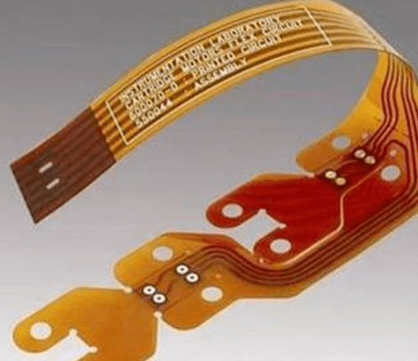
Table of contents
Hide
The Evolution of FPCB
In the early 20th century, innovators in the budding telephone industry identified the need for standardized, malleable electric circuits. These circuits consisted of alternating conductor and insulator layers. A 1903 British patent documented a method involving paraffin-coated paper with flat metal conductors. Concurrently, Thomas Edison proposed using linen paper smeared with cellulose gum and sprinkled with graphite powder.
By the late 1940s, with the onset of mass production, numerous patents surfaced detailing the photo-etching of circuits onto flexible materials. The incorporation of active and passive elements into flexible circuits culminated in the birth of “flexible silicon technology.” This technology integrates semiconductors, like thin-film transistors, onto pliable substrates. This fusion of computational and sensory capabilities paved the way for groundbreaking advancements in aviation, healthcare, and consumer electronics.
What Is FPCB?
Unlike traditional PCBs, FPCBs have distinct design, production, and functionality attributes. In modern manufacturing, “printed” might be a misnomer as photo-imaging or laser-imaging techniques have replaced mainly actual printing. To construct an FPC, metal traces are adhered to a dielectric material, typically Polyimide.
The dielectric layer’s thickness can vary between .0005 inches to .010 inches, while the metal layer’s thickness ranges from .0001 inches to greater than .010 inches. At the same time, adhesives often bond metals to substrates, and alternative methods like vapor deposition are employed. Copper, prone to oxidation, is typically shielded with a protective layer, commonly gold or solder, due to their conductivity and environmental resistance. Dielectric materials insulate the circuitry in non-contact areas to prevent oxidation or unintentional short circuits.
FPCB Composition
Like their rigid counterparts, flexible PCBs can consist of one, two, or multiple circuit layers. A typical single-layer flexible PCB includes the following components:
-
- The dielectric substrate film acts as the core foundation for the PCB. Polyamide (PI), a widely preferred material, boasts excellent tensile and thermal resistance.
-
- Electrical conductors made of copper form the circuit pathways.
-
- A safeguarding layer is provided, often through a cover lay or cover coat.
-
- An adhesive, commonly polyethylene or epoxy resin, binds the different circuit elements together.
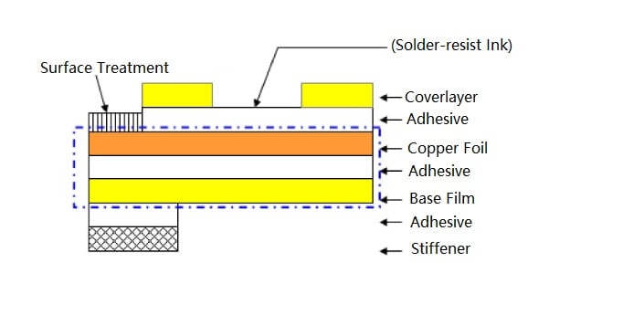
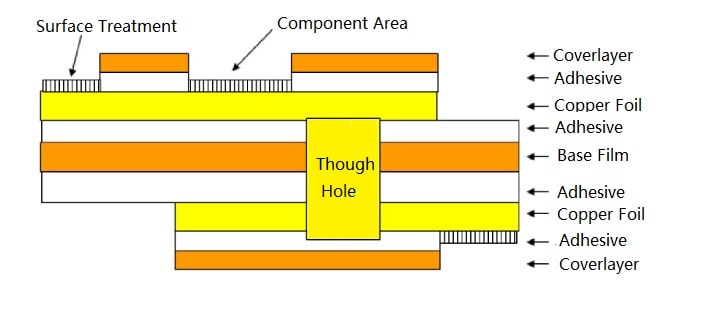
Initially, copper is etched to expose the circuit traces. The protective layer, known as the cover layer, is punctured to expose the solder pads. These components are then cleansed and combined in a rolling process to form the final product. External pins and terminals undergo a tin dipping process, which facilitates soldering and provides resistance against rust. Transitioning to a dual-layer or multi-layer FPC is crucial for intricate circuits or those requiring copper ground shields. The production process of multi-layer FPCs resembles that of single-layer ones. However, multi-layer FPCs incorporate a PTH (Plated Through Hole) to bridge the conductive layers. Adhesive materials bond the conductive pathways to the dielectric base, and in multi-layer circuits, they hold various layers together. Moreover, this sticky layer shields the flexible circuit from potential harm from moisture, dust, and other contaminants.
FPCB Manufacturing Overview
Designing and fabricating a PCB involves a series of intricate steps. Let’s delve into each phase of this process.
-
- Schematic Creation: Before utilizing CAD tools for board design, it’s imperative to complete the design of library components. This involves creating logical symbols for components like resistors, capacitors, inductors, connectors, and ICs. Once prepared, arrange them systematically on schematic sheets via CAD. After positioning the elements, interconnect them by drawing wires, ensuring clarity and readability.
-
- Circuit Simulation: Upon finalizing the schematic design, the next step is to test its functionality. Engineers use tools like SPICE for circuit simulations, allowing them to validate their designs before hardware production, ensuring cost-effectiveness and efficiency.
-
- Setting Up CAD Tools: Modern design tools offer PCB designers many features, including set design rules and constraints to maintain adequate spacing and prevent overlapping—additional means, such as design grids, aid in systematically placing components and tracing routes.
-
- Layout Component Placement: With the schematic data in place, commence the actual circuit board layout. Start by placing component footprints within the board outline in the CAD. When selected, these footprints show their net connections, guiding designers on optimal placement considering factors like electrical noise, physical barriers, and manufacturing ease.
-
- PCB Routing: With all components set, it’s time to interconnect them. Utilize CAD programs to form lines and planes based on the schematic. Features like automatic routing significantly reduce design time. However, ensure routes are designed to maintain signal integrity, avoiding areas with potential noise interference.
-
- Creating a Defined PCB Return Current Path: Essential components like ICs need a connection to power and ground nets. Achieve this by creating solid planes in specified areas or layers. However, designing power and ground planes requires precision. They serve the dual purpose of providing energy and facilitating signal return paths. Inefficient plane design could compromise PCB performance.
-
- Final Rule Verification: Once component placement, trace routing, and plane formation are complete, embed necessary markings, which will be silk-screened on the board’s exterior. Incorporate details like component names, production dates, and copyrights. Moreover, ensure you have a set of manufacturing drawings and utilize tools to estimate production costs.
-
- Board Fabrication: With the output data files ready, dispatch them to a manufacturing unit. Once the board layers are carved and pressed, you’ll have a “bare board.” This board then proceeds to the assembly phase, where components are soldered. After passing all quality checks, your board is production-ready.
Materials Utilized in FPCB Production

FPCB (Flexible Printed Circuit Board) products are uniquely crafted with flexible materials that are lightweight and thin. Such is their resilience that they can be stretched multiple times without damaging the insulation. However, the inherent plastic nature of the board and its wire constitution mean it’s unsuitable for high-current or high-voltage applications. Thus, its application is primarily in low-power, low-current electronic devices.
Soft boards are seldom chosen as the primary carrier in product design because of the substantial unit cost, primarily influenced by Polyimide (PI) material. As a result, they are predominantly incorporated into specific design segments that require flexibility. Components like the electronic zoom lens of a digital camera or the read-head circuitry in optical disc drives exemplify this.
PI, short for Polyimide, has two main varieties: wholly and semi-aromatic. The choice between them depends on their molecular structure and heat resistance. Completely aromatic PI stands out as a direct category of this material. Some materials, like the semi-aromatic PI (a polyetherimide), have rigid or flexible characteristics. Such materials can’t be reshaped once set but can be manipulated in other ways, like crushing or sintering. Since semi-aromatic PI is thermoplastic, injection molding is a standard production method. In contrast, processes such as lamination molding of impregnated materials, compression molding, and transfer molding are preferred for thermosetting PI, demanding specific raw material properties.
Varieties of FPCB
Flexible printed circuit boards (PCBs) come in various configurations, ranging from single-layer designs to complex multi-layer and rigid formats. Here’s a breakdown of some prevalent FPCB designs:
-
- Single-sided Flex Circuits: This design features a single copper layer sandwiched between two insulation layers or one insulated layer with an exposed side. The circuit pattern is etched into the copper, and the design allows the integration of components, connectors, pins, and stiffeners.
-
- Dual Access Single-sided Flex Circuits: Some single-layer FPCBs offer dual access, meaning the circuitry can be accessed from both sides. This is achieved by designing a flexible PCB that allows access to the copper layer through its base insulating layer.
-
- Double-sided Flex Circuits: These have two conducting layers separated by an insulation layer, typically Polyimide. Connections between layers can be achieved in various ways, including through plated holes. Like their single-sided counterparts, these can also accommodate extra components.
-
- Multi-layered Flex PCBs: Incorporating three or more conductive layers separated by insulation, these circuits can be designed as single or double-sided. Standard features include copper-plated through-holes spanning the circuit’s thickness. These designs often address challenges like signal crossovers, impedance, and shielding.
-
- Rigid-flex Circuits: A combination of rigidity and flexibility, these usually comprise multiple conductive layers separated by rigid or flexible insulation. Their unique construction, which excludes standard stiffeners, has made them a preferred choice in the aerospace and defense sectors.
-
- Aluminum Flex Boards: Primarily found in high-power applications like medical devices and automobiles, these circuits are compact, cost-effective, and efficient at heat dissipation due to their aluminum layers.
-
- Microcircuits: Tailored for consumer electronics, these lightweight, shock, and vibration-resistant circuits ensure excellent signal integrity despite their miniature size.
-
- HDI Boards with Flex Circuits: Marking a revolution in PCB technology, these boards, equipped with more connectors than traditional ones, enhance electrical performance. They’re commonly used in smartphones, PCs, and gaming consoles.
-
- Ultra-thin Flex PCBs: Designed for ultimate portability and even biocompatible applications, these circuits are incredibly lightweight and slim, making them ideal for wearable or implantable tech.
This overview provides insight into the diverse world of flexible printed circuit board designs and their applications.
Flex PCB Usage
A flex PCB mirrors the features of a conventional printed circuit board, but it’s constructed using a malleable base material. It’s notably beneficial for temporary setups due to its durability and compact design. The technology’s versatility has made it prevalent across numerous sectors. Here are some areas where it’s making a difference:
-
- Automotive Sector: As vehicles increasingly incorporate electronics, their circuits must withstand on-road shocks. Flex PCBs are economically viable and durable, making them ideal for automotive applications.
-
- Consumer Electronics: Devices like smartphones, tablets, cameras, and video recorders benefit from flex PCBs. Their resilience to frequent movement, shocks, and vibrations makes them indispensable in these gadgets.
-
- High-Frequency Applications: Flex PCBs are suitable for high-speed digital, RF, and microwave functions due to their consistent performance.
-
- Industrial Electronics: Given the operational demands, industrial electronics require PCBs that resist significant stress and vibrations. Flex PCBs aptly meet this criterion.
-
- LED Lighting: LEDs are progressively replacing traditional lighting. The efficacy of LED technology is enhanced with flex PCBs, especially given their ability to manage heat.
-
- Medical Systems: The escalating need for electronic implants and compact surgical tools necessitates compact electronic designs. Flex PCBs, with their flexibility and resilience, fit seamlessly into medical equipment and implantable devices.
-
- Power Electronics: For gadgets operating at peak loads, flex PCBs can carry higher currents due to their adaptable copper layers, positioning them as a staple in power electronics.
Understanding Flexible Printed Circuit Boards (FPCB)
Flexible printed circuit boards, or FPCBs, are valuable because they can be bent, making them suitable for dynamic and static scenarios. Unlike their rigid counterparts, these flexible boards are resilient enough to be stretched in dynamic applications without any damage. They are especially effective for borehole measurements in the oil and gas sector due to their ability to withstand extreme temperatures ranging from -200° C to 400° C. While flexible boards have specific applications, they aren’t always an ideal replacement for traditional PCBs. Conventional rigid boards remain popular due to their cost-effectiveness, especially in automated, high-volume production. Nonetheless, for requirements prioritizing performance, precision, accuracy, and repeated bending, FPCBs are indispensable.
The Challenges and Expenses of Utilizing FPCB
Using FPCBs is not without its challenges. For instance, making design alterations or conducting repairs can be complex. Any design changes necessitate a new foundational map or an update to the lithography software. Furthermore, modifying the board requires the removal of its protective layer, complicating the process. The manufacturing of these boards also has size constraints because of the machinery dimensions. Additionally, FPCBs are fragile and demand careful handling; only skilled professionals should solder and repair them.
Regarding budget considerations, the specific use case determines the cost-effectiveness of FPCBs relative to rigid PCBs. Each FPCB project is unique, and upfront costs like circuit design, layout, and photographic plate production can be steep, particularly for smaller batches. However, in larger production quantities, FPCBs might prove to be more economical. Reducing components such as wires, connectors, and wire harnesses needed for assembly is significant in this cost-effectiveness. Furthermore, their streamlined supply chain risk advantages and decreased maintenance due to fewer component requirements also make them a compelling choice.
Enhanced Features of FPCB
The flexible circuitry sector has been on a consistent rise. With this expansion, several technological advancements have emerged:
-
- Graphic Overlays: These are acrylic or polyester shields for PCBs, facilitating user interaction with the circuitry below. They typically feature LEDs, LCDs, and switches, enhancing the user’s control over the PCB.
-
- Hot Bar Soldering: This offers an alternative to traditional connectors by bridging hardboards with flex circuits. It’s not only cost-effective but also provides a durable and long-lasting connection.
-
- Laser Skived Slots and Holes: Gone are the days when FPCBs were manually sliced using blades, where precision hinged on the operator’s skill. Modern lasers ensure exact and controlled cuts, paving the way for even tinier circuits on flexible PCBs.
-
- Panelization: Grouping circuit boards, or PCBs, into large panels comprising multiple modules can accelerate the assembly process in “pick-and-place” production lines. The subsequent step is segmenting these units for finer applications.
-
- Pressure-Sensitive Adhesives: These adhesives bond components simply by peeling off a liner and pressing the item onto the adhesive layer. They’re frequently employed in PCBs, securing circuit elements without the necessity of solder.
-
- Shielding: Electromagnetic interference is used to pose significant challenges, particularly in environments susceptible to it. Thanks to advancements in shielding techniques, such disturbances have been minimized, enhancing signal line control and impedance.
-
- Stiffeners: Incorporating materials like FR4 and Polyimide, stiffeners bolster flex circuits, especially at connection junctures that require additional support. This augmentation ensures the circuit’s longevity and optimum performance.
Advantages of FPCB
Flexible Printed Circuit Board (FPCB) technology paves the way for innovative product designs and configurations. Its adaptability is highly valued in components like connectors, wires, cables, and PCBs. Here are the notable benefits of flex circuits:
-
- FPCBs significantly reduce device weight by around 70%.
-
- They offer enhanced options for electronic packaging.
-
- Due to their flexibility and adaptability, FPCBs resolve challenges in packaging and wiring.
-
- FPCBs minimize the requirement for wires, connectors, PCBs, and cables, streamlining connection processes.
-
- Their material’s flexibility and thinness enable 3D packaging.
-
- Electrical integration with FPCBs is straightforward, offering diverse material choices and various plating methods.
-
- FPCBs efficiently dissipate heat, making them suitable for high-power applications.
-
- They ensure consistent mechanical and electrical performance.
-
- FPCBs are approximately 30% more cost-effective than conventional wiring and assembly techniques.
-
- They consume roughly 30% less space.
-
- FPCBs enhance reliability by eliminating potential wiring errors.
Disadvantages of FPCB
However, like all technologies, FPCBs have their challenges:
-
- The initial design, wiring, and imaging masters for a flex circuit are costly, especially when tailored for specific applications. Hence, they may not be economical for low-volume production.
-
- Repairing or replacing flex circuits can be cumbersome. Alterations often require modifications from the original design or the software blueprint. Moreover, the protective surface layer needs removal and reapplication during repairs.
-
- Due to their compact nature, FPCBs are typically produced in batches. Their dimensions are limited by the machinery’s capacity, restricting their length and width.
-
- Careless handling or incorrect installation can easily damage FPCBs. Proper soldering and modifications demand skilled personnel.
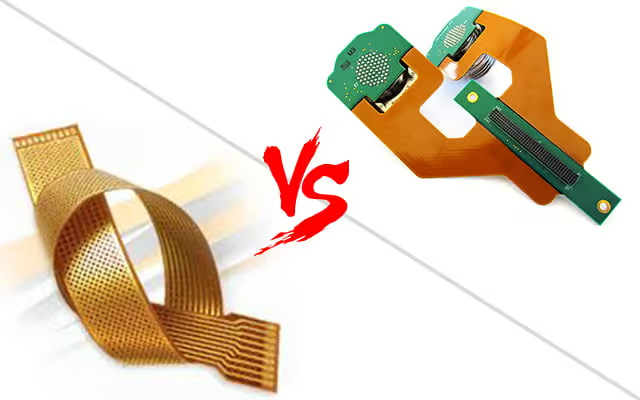
Distinguishing Rigid and Flexible PCBs
Most envision a solid, rigid circuit board when they think of PCBs. Such panels are placed over a non-conductive substrate, interconnecting electronic components through conductive pathways. Typically, glass is the insulating layer for these rigid PCBs, ensuring strength and durability. This rigidity not only provides firmness but also prevents components from overheating. While traditional PCBs are made from materials like copper or aluminum, there are flexible versions crafted from bendable materials like Polyimide. These flexible PCBs are adept at withstanding shocks, dissipating excess heat, and being molded into various shapes. Their flexibility primarily benefits contemporary miniaturized electronic gadgets, leading to increased adoption. Notable distinctions between rigid PCBs and flex circuits include:
-
- Rolled annealed copper, being more malleable than electro-deposited copper, is the preferred choice for conductive material in flex circuits.
-
- In production, overlays can be employed as an alternative to solder masks, safeguarding the exposed circuitry on a flexible PCB.
-
- While flexible PCBs tend to be pricier, their compact nature allows engineers to design smaller devices. Thus, the indirect savings can outweigh the initial cost difference.
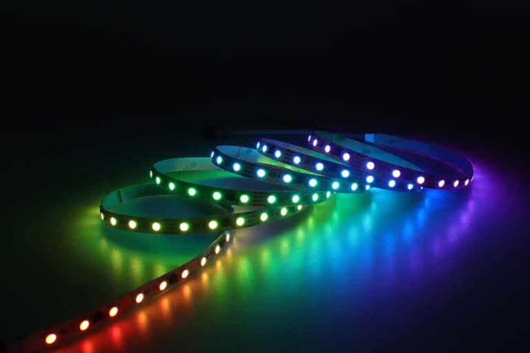
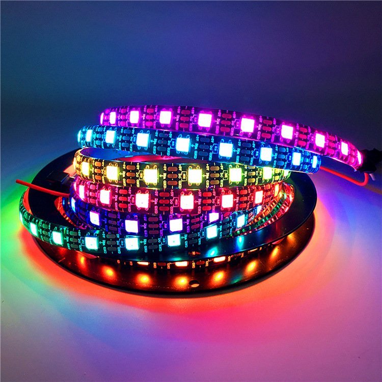
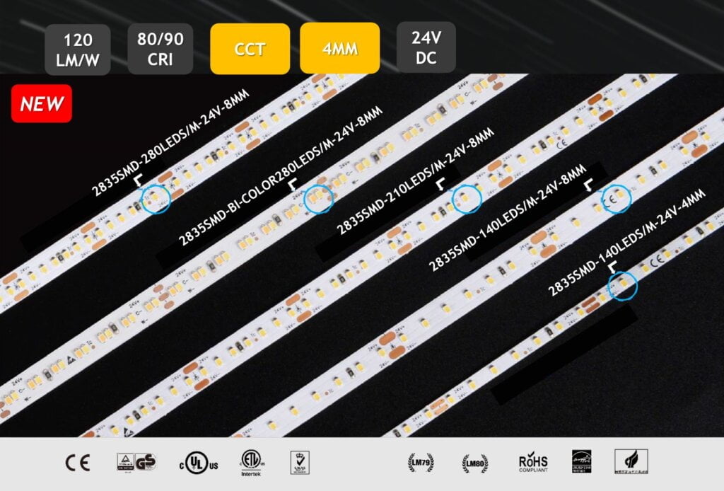
The Role of FPCB in LED Strips
With technological advancements, LED strips are gaining immense popularity. They offer an excellent solution for illuminating and decorating spaces, and introducing flexible PCBs (FPCB) elevates their performance. LED strips consist of interconnected circuit boards. Creating these flexible printed circuit boards relies on Surface Mount Technology (SMT), which uses surface-mounted components like SMD LEDs and connectors. The FPCB serves as a foundation when assembling LED chips. A pivotal aspect of any circuit board is its heat dissipation capability. Flexible electronics play a crucial role in enhancing the efficiency of LED strip lights. Like their rigid counterparts, FPCBs come in single-layer, double-layer, and multi-layer configurations.
Key Takeaways
-
- FPCBs are versatile, allowing bending and flexing to conform to varied shapes and sizes, simplifying their design and application.
-
- Flexible circuits adapt seamlessly, Unlike rigid circuits with limitations in accommodating unconventional dimensions.
-
- They occupy minimal space on the main board, resulting in cost savings and reduced bulkiness.
-
- Optimal space utilization and superior thermal management ensure efficient heat distribution.
-
- Flexible printed circuits offer more reliability and durability than rigid PCBs, especially under frequent movement or mechanical stress conditions.
-
- Traditional connectivity methods, reliant on soldered wires and manual connectors, have been outpaced by FPCBs. Their lightweight, slimness, mechanical strength, tolerance to high temperatures, resistance to environmental factors, and effective EMI management make them superior.
-
- Imagine modern cars with intricate electronics, like rotary controls and displays. Often subjected to mechanical stresses and vibrations, these systems demand robust connections. FPCBs guarantee uninterrupted operation, longevity, and minimal upkeep in the automotive realm.
MyLikeLed: Your Partner in Quality LED Solutions
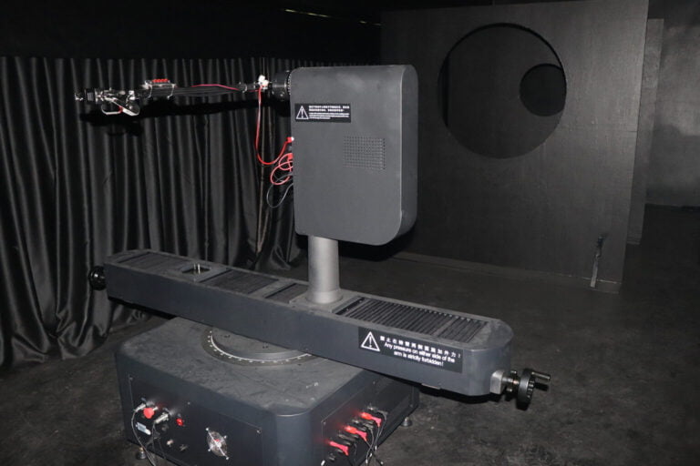
At MyLikeLed, we prioritize delivering top-tier LED strips and LED neon flex. Our products undergo rigorous testing in advanced laboratories to guarantee unparalleled quality. Furthermore, we provide personalized choices for our LED strips and neon flex. For premium LED lighting solutions, reach out to MyLikeLed today!

Hi, I’m Xylia Xiong, a sales professional with 14 years of experience in the LED strip light industry. I specialize in providing tailored solutions, leveraging my expertise in LED products and the latest industry trends. Known for effective communication and problem-solving, I’m dedicated to helping lighting manufacturers, importers, and distributors achieve their goals.
Let’s work together to create customized solutions that exceed expectations.