Numerous options are available for LED strip lights in the market. When we intend to purchase LED strips, it becomes crucial to assess their quality. One of the simplest ways to do so is by requesting an “integrating sphere test report” from the LED strip manufacturer. This report provides valuable information about various product parameters, enabling a preliminary evaluation of its quality. However, since the integrating sphere test report contains several parameters, it can be challenging for many individuals to comprehend.
This article aims to explain each parameter mentioned in the integrating sphere test report. By reading this article, you will clearly understand the integrating sphere test report, facilitating future comprehension. Let’s dive in and explore this topic further.
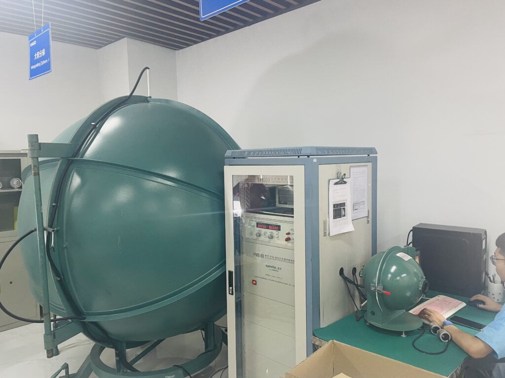
Table of contents
Hide
An Integrating Sphere: A Comprehensive Explanation
An integrating sphere, an Ulbricht sphere, represents an optical component characterized by a hollow spherical cavity. The inner surface of this cavity is coated with a diffuse white reflective material, and small openings serve as entrance and exit ports. The primary attribute of an integrating sphere is its capability to scatter or diffuse light uniformly. When light rays reach any point on the inner surface, they undergo multiple scattering reflections, distributing the light evenly to all other points within the sphere. Consequently, the original direction of the light becomes inconsequential as its effects are minimized.
An integrating sphere can functionally be likened to a diffuser that maintains power while eliminating spatial information. Typically, it is employed with a light source and a detector to measure optical power. Another similar device worth noting is the focusing or Coblentz sphere, which features a specular (mirror-like) inner surface rather than a diffuse one. I recommend visiting a source dedicated to integrating sphere for further in-depth information.
Integrating Sphere Test Report Overview
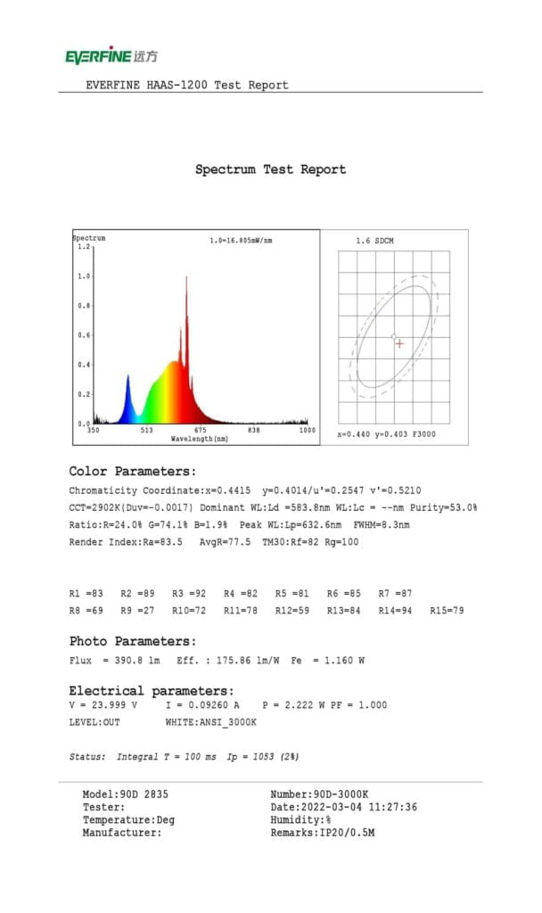
Below is an overview of the test report generated by our factory’s integrating sphere. The report comprises seven distinct sections, as outlined below:
- Header
- Relative Spectral Power Distribution
- Colour Consistency Macadam Ellipse
- Colour Parameters
- Photometric Parameters
- Instrument Status
- Footer
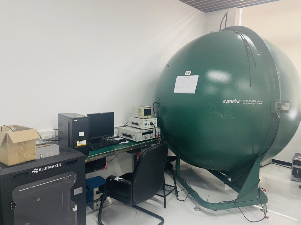
1. Header
The header contains the brand and model information of the integrating sphere. EVERFINE manufactures our company’s integrating sphere, and the model is HAAS-1200. EVERFINE Corporation (Stock Code: 300306) is a reputable supplier of photoelectrical measurement instruments and calibration services. They are industry leaders in the field of LED and lighting measurement instruments. EVERFINE is recognized as a National Certificated High-tech Enterprise, a Supportive Member of the CIE, an ISO9001 Registered Firm, and a Government Certificated Software Enterprise & Software Product Enterprise. Additionally, they possess a Province Level High-tech R&D Center, NVLAP, accredited Lab (Lab code 500074-0) and CNAS accredited Lab (Lab code L5831). In 2013 and 2014, EVERFINE was recognized by Forbes as one of China’s Most Potential Listed Companies.
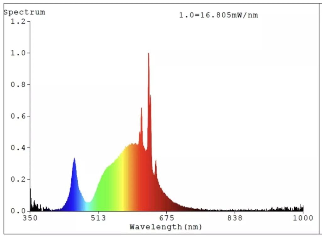
2. Spectral Power Distribution
In radiometry, photometry, and colour science, a spectral power distribution (SPD) measurement characterizes the power per unit area per illumination wavelength, also known as radiant exitance. In a broader sense, the term spectral power distribution can denote the concentration, as a function of wavelength, of any radiometric or photometric quantity such as radiant energy, radiant flux, radiant intensity, radiance, irradiance, radiant exitance, radiosity, luminance, luminous flux, luminous intensity, illuminance, or luminous emittance.
Relative Spectral Power Distribution
The relative SPD is obtained by comparing the spectral concentration (irradiance or exitance) at a particular wavelength to the concentration at a reference wavelength. Mathematically, this is expressed as:

For example, the management of luminance in lighting fixtures and other light sources is carried out individually. A spectral power distribution is often adjusted or standardized in some way, commonly to a value of unity at 555 or 560 nanometers, corresponding to the peak of the eye’s luminosity function.
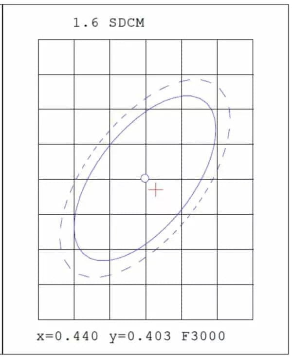
3. MacAdam Ellipse and Color Consistency
The concept of colour consistency is assessed using MacAdam ellipses, initially introduced in the 1930s by David MacAdam and his colleagues. These ellipses represent a chromaticity diagram, encompassing a region that includes all colours indistinguishable from the centre colour by the average human eye.
MacAdam conducted experiments using visual observation of the Just Noticeable Colour Difference (JND) between two closely matched coloured lights. The JND is the degree of colour difference at which 50% of observers perceive a distinction, while the other 50% do not notice any difference. In the CIE 1931 2-degree observer colour space, the zones with standard deviations of colour matching (SDCM) were discovered to possess an elliptical shape. The size and orientation of these ellipses varied significantly depending on the position within the colour space diagram. Notably, the ellipses were most extensive in the green region and smaller in the red and blue regions.
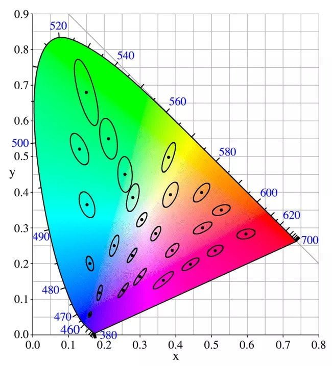
The colour produced by white light LEDs can vary, making quantifying the colour difference within a batch or bin of LEDs worthwhile. One convenient measure for expressing this difference is the number of SDCM (MacAdam) ellipses steps in the CIE colour space that the LEDs fall into. Most people won’t perceive any colour difference when the chromaticity coordinates of a group of LEDs all fall within 3 SDCM (or a “3-step MacAdam ellipse”). However, some colour difference becomes noticeable if the colour variation extends to 5 SDCM or a 5-step MacAdam ellipse. According to the test report, the colour consistency is 1.6SDCM, and the ellipse’s centre point is “x=0.440 y=0.403”, as indicated by “F3000” at the bottom.
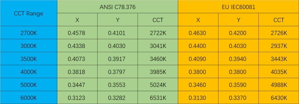
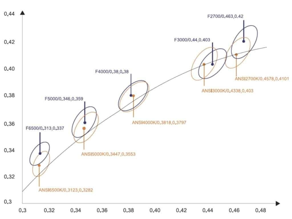
Main Categories of Color Tolerance Standards
Currently, the predominant colour tolerance standards in the market encompass the North American ANSI and European Union IEC standards. The central points of colour tolerance corresponding to these standards can be summarized as follows:
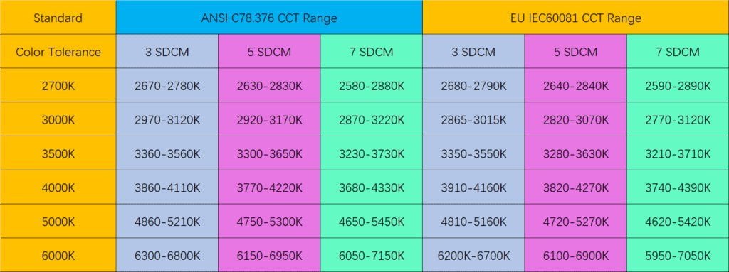
3-SDCM Schematic diagram comparing IEC standard and ANSI standard
4. Color Parameters
The Color Parameters section encompasses various elements such as Chromaticity Coordinate, Correlated Color Temperature (CCT), Dominant Wavelength, Peak Wavelength, Purity, Ratio, Full Width at Half Maximum (FWHM), and Rendering Index (Ra, AvgR, TM30:Rf, TM30:Rg).
Chromaticity Coordinate
The CIE 1931 color spaces establish a quantitative connection between the distribution of wavelengths in the visible spectrum of electromagnetic radiation and the colours perceived by the human color vision. These colour spaces, defined by mathematical relationships, are crucial for color management in various applications, including colour inks, illuminated displays, and digital cameras. The system was developed in 1931 by the “Commission Internationale de l’éclairage” International Commission on Illumination.
The CIE 1931 RGB colour space and CIE 1931 XYZ colour space were introduced by the International Commission on Illumination (CIE) in 1931. These colour spaces were formulated based on a series of experiments conducted in the late 1920s by William David Wright with ten observers and John Guild with seven observers. The experimental findings combined define the CIE RGB colour space, the foundation for the CIE XYZ colour space.
Despite their age, the CIE 1931 colour spaces continue to be widely used, along with the 1976 CIELUV colour space.
In the CIE 1931 model, luminance is represented by Y, quasi-equal to blue is denoted by Z (in the context of CIE RGB), and X is a combination of the three CIE RGB curves selected to ensure non-negativity (refer to the definition of the § Definition of the CIE XYZ color space). An advantageous outcome is achieved by setting Y as the luminance: for any given Y value, the XZ plane encompasses all possible chromaticities at that luminance.
The CIE 1976 L*, u*, v* color space, also known as CIELUV, is a colour space that was adopted by the International Commission on Illumination (CIE) in 1976 for colourimetry. It was developed as a computationally simple transformation of the 1931 CIE XYZ colour space to achieve perceptual uniformity. CIELUV is widely used in various applications, including computer graphics with coloured lights. It’s important to note that while additive mixtures of different coloured lights can be represented by a line in CIELUV’s uniform chromaticity diagram (known as the CIE 1976 UCS), these mixtures will not necessarily fall along a line in the CIELUV colour space unless the mixtures maintain a constant lightness, contrary to popular belief.
CCT
Colour temperature, also known as Correlated Color Temperature (CCT) in the field of lighting technology, indicates the perceived yellow or blue hue of the light emitted by a light bulb. This measurement is expressed in Kelvin units and typically ranges from 2200 Kelvin degrees to 6500 Kelvin degrees.
Dev
What exactly is Duv?
In essence, Duv is a standard of measurement known as “Delta u,v.” This standard is used to calculate the colour point’s distance from what is known as the black body curve of light. It should not be mistaken with Delta you’,v’.
Typically, Duv is used along with a metric called the correlated colour temperature (CCT) to depict how closely a particular light source mirrors the “pure white” of the black body curve.
If the colour point’s value is negative, it suggests that it is situated beneath the black body curve, implying a magenta or pink hue. On the other hand, a positive value signifies a point above the black body curve, demonstrating a green or yellow hue.
A colour point’s distance from the black body curve—both in terms of its magnitude and direction—is conveniently represented by the Duv value. A more prominent positive value points to a location further above the curve, while a more significant negative value indicates a location further below the curve.
Significance of Duv
When dealing with colour-sensitive lighting contexts like film and photography, Duv becomes a crucial metric. The CCT alone does not offer sufficient information about a colour’s shade.
In the attached graphic, you can observe iso-CCT lines for various CCT values. These lines indicate points with the same CCT value.
For example, for a CCT value of 3500K, the corresponding iso-CCT line transitions from a yellowish tint in the region above the black body curve (higher Duv value) to a pink/magenta tint as it descends below the black body curve (lower, negative Duv value).
Hence, a lamp with a CCT value of 3500K could, in practice, be located anywhere along this iso-CCT line.
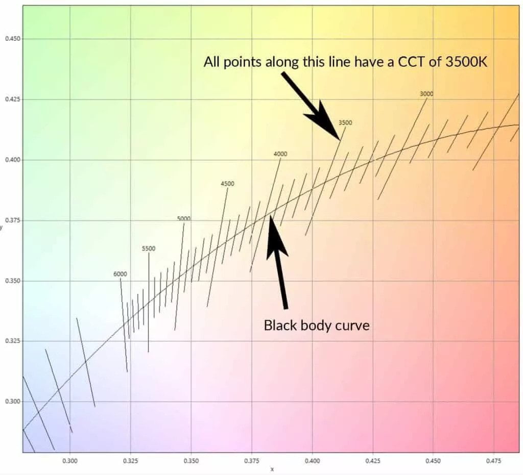
Alternatively, suppose we were to receive details that a lamp possesses a CCT value of 3500K and a Duv of 0.001. These specifics would be enough to indicate that it aligns with the 3500K iso-CCT line, minutely above the black body curve. A valid colour point can be identified only when both Duv and CCT values are supplied.
Dominant Wavelength
In colour science, the dominant and complementary wavelengths serve as methods to describe any light mixture based on the monochromatic spectral light that induces a similar (and the corresponding contrasting) hue perception. For a specific physical light mixture, these dominant and complementary wavelengths aren’t entirely set; they fluctuate depending on the colour of the illuminating light, known as the white point, owing to vision’s colour constancy.
Peak Wavelength
Peak wavelength can be described as that solitary wavelength at which the radiometric emission spectrum of the light source hits its peak. Simply put, it isn’t a reflection of any perceived emission from the light source as discerned by the human eye but rather as observed by photodetectors.
Purity
Colour purity refers to the extent to which a colour resembles its true hue. It is deemed pure if a colour isn’t combined with black or white. Colour purity is especially beneficial when mixing colours, as starting with a pure colour offers a broader range of possibilities to produce varying tones, shades, and tints.
Ratio
The term ratio denotes the proportional relationship between the red, green, and blue amounts in the mixed light.
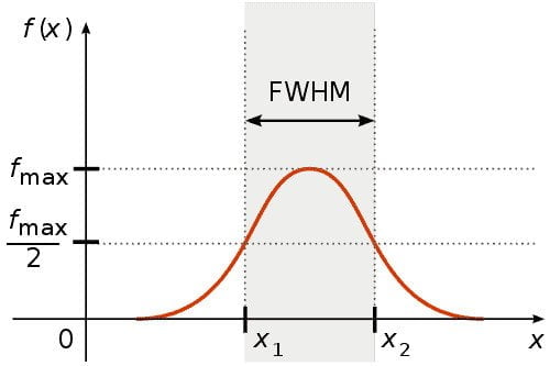
FWHM
In a distribution, the full width at half maximum (FWHM) signifies the difference between the two points of the independent variable at which the dependent variable equals half of its highest value. Simply put, it measures a spectrum curve’s width between the points on the y-axis at half the maximum amplitude. If the function is symmetric, the half width at half maximum (HWHM) would be half of the FWHM.
Color Rendering Index (CRI)
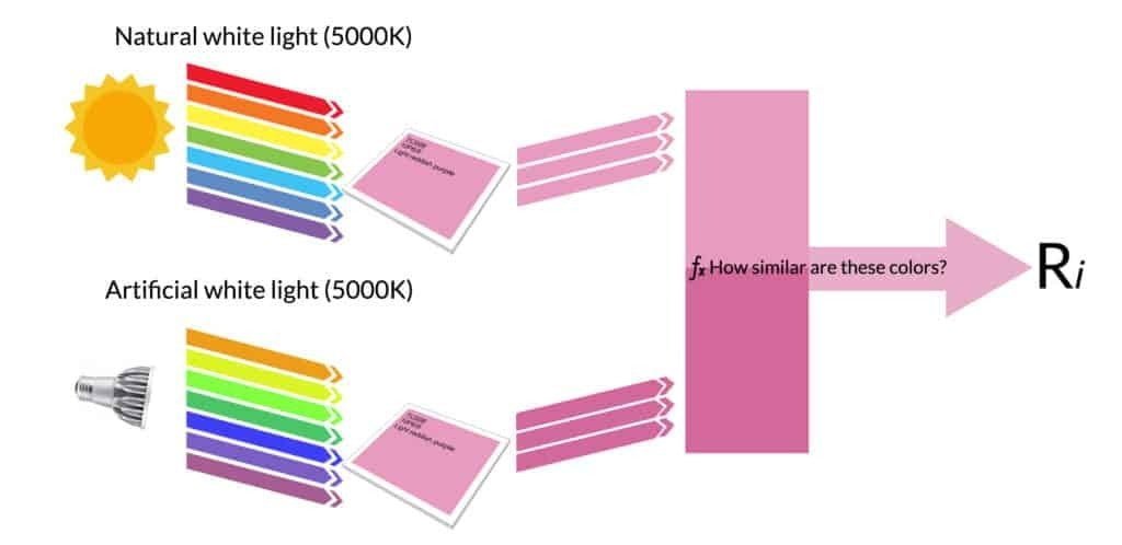
A Color Rendering Index (CRI) serves as a numerical indicator that measures the capacity of a light source to accurately portray the colours of various objects when compared to a natural or standard light source.
How do we measure CRI?
The procedure of measuring CRI closely resembles the visual assessment example provided earlier. However, it involves algorithmic computations after measuring the spectrum of the light source under consideration.
The first step is determining the colour temperature for the examined light source, which can be deduced from spectral measurements.
It’s crucial to establish the light source’s colour temperature to select the corresponding daylight spectrum for comparison.
Next, the light source under study is virtually projected onto a set of virtual colour patches known as test colour samples (TCS), and the colour reflection is measured.
A total of 15 colour patches are used in the measurement:
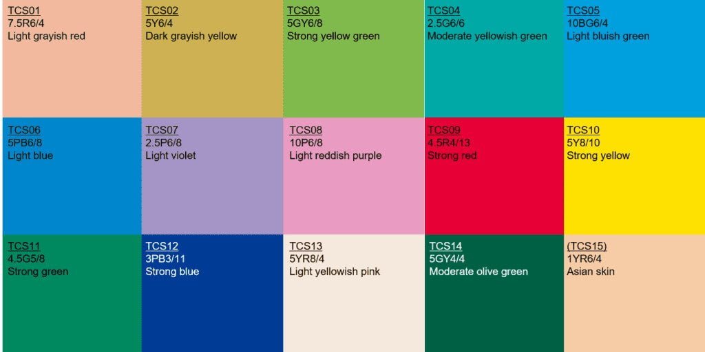
In addition, we will have a series of virtual measurements capturing reflected colours under natural daylight conditions with matching colour temperatures. Ultimately, we can systematically calculate each colour swatch’s “R” score by comparing these reflected colours.
The R-value associated with a specific colour shows how accurately a light source can reproduce that colour. Thus, a light source’s overall colour rendering performance for a wide range of colours is determined by calculating the average of these R values via the CRI formula.
Ra symbolizes the mean value of R1-R8.
AvgR represents the average value of R1-R15.
TM30
The Illuminating Engineering Society (IES) recently introduced TM30, a novel quality metric meant to complement and eventually supersede the outdated CRI (CIE) Metric for assessing light source fidelity.
Primary Components of TM30
- Rf is a metric analogous to the CRI (Ra) standard, comparing colour rendering to a palette of 99 colours (as opposed to CRI’s 9)
- Rg measures the average gamut shift (hue/saturation) of the source
- A visual illustration of Rg to display which colours are muted or more vibrant due to the light source
For more in-depth information, you can download the PDF titled “Evaluating Color Rendition Using IES TM-30-15“.
5. Parameters in Photometry
Luminous Flux
In photometry, luminous flux, also referred to as luminous power, quantifies the perceived strength of light. This is different from radiant flux, which quantifies the overall power of electromagnetic radiation, encompassing infrared, ultraviolet, and visible light. The distinction is that luminous flux is adjusted to incorporate the diverse sensitivity of the human eye to different light wavelengths.
The lumen (lm) is the standard unit of luminous flux in the International System of Units (SI). Before 19 May 2019, a lumen was defined as the luminous flux stemming from a light source emitting one candela of luminous intensity over a solid angle of one steradian. However, from 20 May 2019 onwards, the definition of a lumen was fixed by setting the luminous efficacy of monochromatic radiation of frequency 540×1012 Hz (equivalent to green light with a wavelength of 555 nm) to be 683 lm/W. As a result, a 1-lumen source emits approximately 1/683 W or 1.146mW.
In various other unit systems, luminous flux might be defined in power units.
Luminous flux incorporates the eye’s sensitivity by adjusting the power at each wavelength according to the luminosity function, which signifies the eye’s response to different wavelengths. Thus, luminous flux represents a weighted sum of the power across all wavelengths within the visible band, with light outside this band excluded.
Luminous Efficacy
Luminous efficacy acts as an indicator of how efficiently a light source generates visible light. It represents the ratio of luminous flux to power, expressed in lumens per watt in the International System of Units (SI). Depending on the context, the power may refer to the radiant flux of the source’s output or represent the total power (like electric or chemical energy) used by the source. The term’s intended meaning usually needs to be derived from the context and can occasionally be ambiguous. The former interpretation is sometimes called the luminous efficacy of radiation, while the latter is termed the luminous efficacy of a light source or overall luminous efficacy.
Radiant Flux (Fe)
Radiant flux, or radiant power, refers to the amount of radiant energy emitted, reflected, transmitted, or received per unit of time. Spectral flux or spectral power, on the other hand, represents the radiant flux per unit frequency or wavelength, depending on whether the spectrum is measured in terms of frequency or wavelength. The standard unit of measurement for radiant flux is the watt (W), equivalent to one joule per second (J/s). In the case of spectral flux measured in frequency, the unit is the watt per hertz (W/Hz), while for spectral flux measured in wavelength, the unit is the watt per meter (W/m), commonly expressed as the watt per nanometer (W/nm).
6. Electrical Characteristics
Voltage (V)
Voltage, often referred to as electric potential difference, electric pressure or electric tension, is the discrepancy in electric potential between two distinct points. The voltage calculation in a static electric field is the amount of work required per charge unit to transfer a test charge from one point to another. The International System of Units recognizes the derived unit for voltage (or potential difference) as a volt. The LED strip lights we provide typically operate on either 24V or 12V.
Electric Current (I)
Electric current is a flow of charged particles, such as electrons or ions, traversing through an electrical conductor or open space. The net rate of flow of electric charge across a boundary or into a specific volume quantifies the current. These flowing particles are identified as charge carriers, which could be several types of particles, depending on the conductor. For instance, in electric circuits, charge carriers are predominantly electrons travelling through a wire. In the case of semiconductors, charge carriers could either be electrons or holes. For electrolytes, ions are the charge carriers; in plasma or ionized gas, ions and electrons are charge carriers.
The SI unit for electric current is the ampere, represented as ‘A’, which represents the flow of electric charge across a surface at one coulomb per second. It is one of the SI base units. An ammeter is typically used to measure electric current.
Power Consumption (P)
In electrical engineering, power consumption denotes the quantity of electrical energy consumed per unit of time, typically used to operate appliances or devices. The measurement units for power consumption are usually in watts (W) or kilowatts (kW). Power consumption can be calculated by multiplying voltage with the current.
Power Factor(PF)
The power factor of an AC power system in electrical engineering is the ratio between the actual power consumed by the load and the apparent power flowing in the circuit. It is a dimensionless number within the range of -1 to 1. A power factor below one indicates a phase difference between the voltage and current, resulting in a reduced average product. Real power represents the rapid multiplication of voltage and current, representing the electricity’s capability to perform work. On the other hand, apparent power is the product of the RMS current and voltage.
In some instances, the apparent power may exceed the real power due to energy stored in the load and return to the source or a non-linear load distorting the current waveform drawn from the source. When a device, typically the load, generates power that flows back towards the source, a negative power factor occurs.
Within an electric power system, a load with a low power factor draws more current than a load with a high power factor, even if the valuable power transferred is the same. These higher currents increase energy losses in the distribution system and necessitate larger wires and additional equipment. Due to the expenses associated with larger equipment and wasted energy, electrical utilities typically apply higher costs to industrial or commercial customers who exhibit a low power factor.
7. Instrument Conditions
The term’ Integral T‘ signifies the duration of integration.
IP signify photoelectric saturation, which is associated with the duration of the chosen integration during the experiment. Ideally, the IP value should exceed 30% for an automatic integration time selection. However, if the integration time is 100 seconds, the IP value will drop below 30%, expediting the testing process without impacting other optoelectronic parameters.
8. Footer
The bottom section carries additional details, including the Model Name and Number, the individual who performed the test (Tester), the date when the test was conducted, environmental conditions such as Temperature and Humidity, the Manufacturer, and any pertinent Remarks.
Upon concluding this article, I am confident that you’ll find no difficulty comprehending all parameters in the integrating sphere test report. Should there be any queries, feel free to drop a comment or transmit a message via the website’s contact form.
Final Thoughts
Grasping the fundamentals of interpreting an Integrating Sphere Test Report is a crucial skill for anyone active in the lighting field. By honing in on essential parameters such as luminous flux, colour rendering index, and colour temperature, knowledgeable choices can be made regarding the selection of lighting sources. Additionally, the report aids in flagging any potential challenges with the light source, facilitating the development of superior and more energy-efficient lighting solutions.
MyLiKeLed is a trusted producer of superior LED strips and LED neon flex. All our merchandise undergoes rigorous testing in advanced laboratories to guarantee top-notch quality. Moreover, we provide various customizable options on our LED strips and neon flex. Therefore, for first-rate LED strips and LED neon flex, get in touch with MyLiKeLed without delay!

Hi, I’m Xylia Xiong, a sales professional with 14 years of experience in the LED strip light industry. I specialize in providing tailored solutions, leveraging my expertise in LED products and the latest industry trends. Known for effective communication and problem-solving, I’m dedicated to helping lighting manufacturers, importers, and distributors achieve their goals.
Let’s work together to create customized solutions that exceed expectations.